|
Clutches (Passive,
Hydraulic, and Electronic):
Most of the more popular LSD systems fall into this category. I'll just get this out of
the way up front. The biggest problem with all clutch systems is that they wear out over
time, but it can be a very long time. And like all clutches they generally have a
fixed upper limit on their torque carrying capacity.
Anyway, how do we get rid of all those fins, liquid, and weight from the VC?
|
Passive Clutch:
Let's try a passive clutch. To the back of one drive gear is attached a set of metal
clutch plates, and to the outside housing are clutch pads. Back this clutch pack with
heavy springs that squeeze the plates between the clutch pads and so on. Again, nothing
happens in normal conditions with equal traction, as both drive gears turn at the same
speed. When one side loses traction and the diff tries to spin that side, the spring
loaded clutch simply imparts a fixed amount of torque back to the other side. With a
passive clutch, it doesn't get better with speed either. If anything it transfers less
torque at higher differential speeds, (dynamic versus static friction). You might be
tempted to add bigger springs to make the clutch engage harder but then you'll end up with
some of the same bad traits of a locking diff under low traction conditions when just
driving around corners at normal speeds when one side will drag and the other spin.
Progressive/Locking Clutch (Positraction or Salisbury
type): 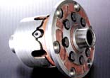
This is probably the most common type of LSD. Here there are a set of clutch plates
attached to the inside of the housing just outside of each drive gear, and a set of clutch
disks attached to the output shafts, but also still inside the housing. There are two
thick pressure rings which attach to the inside of the housing near the spider gear
shafts. The pressure rings push outwards against the clutch packs. The space between the
pressure rings forms an opening that is wedge shaped, and the spider gear shafts
themselves, form the wedge. As power is applied to the ring gear, and transmitted to the
housing, and down into the pressure rings, they start to push on the spider gear shaft
which (depending on traction conditions) wedges itself toward the end of the opening
between pressure rings, which forces the rings away from each other, which applies
pressure to the clutch packs, which locks both drive gears to the outside housing and
under very high power the differential locks up nearly solid.
So this one is power sensitive. Note, there must also be some preload
built in, for use in low traction conditions. This system relies on there being some
resistance to the applied power to cause the pinion gear (spider gear) shaft to wedge open
the pressure rings. If you started with no static clutch pressure, then under very low
traction conditions (one side on ice), there won't be enough resistance to wedge the
pinion shaft in place and it'll remain an open diff. As a result there's usually enough
static load added to provide some constant torque split to both sides, and then if you hit
the gas, it'll lock up the diff and you get torque down to whichever side can use it. I
gleaned much of this information from a Semi Technical Discussion of an LSD
made for Datsun/Nissan trucks. This type of LSD is popular in the 4x4 community as a
compromise between open and full locking, but full locking (air lockers) are still
preferred for serious wheeling. Drag racers also use this type, because it
locks up under high power and keeps the car pointed pretty straight.
|
|
Simple Hydraulic Clutch:
Put the same clutch pack in, but put a hydraulic actuator behind it instead of the
springs. Now, pumping oil into the innards of a rotating mechanism is possible (and I'm
sure has been done) but is hard so instead it's often done in a clever fashion. You attach
a small hydraulic pump to one or more of the spider gears, or a floating gear that spins
at the same speed as the spiders but without carrying the load. The pumps simply scavenge
the oil from wherever they can inside the case and pump it into the actuators behind the
clutch. Remember the spider gears only rotate when the drive gears are rotating at
different speeds. As you can guess, this system is also speed sensitive
as the hydraulic pump only works when one side is spinning faster than the other, but the
hydraulics offer much quicker activation than the viscous coupling from above, and the
clutch pressure can be maintained with less speed differential. We may still have the
clutch wear problem. Also the activation rate is basically fixed by the designers.
|
|
Electronic Clutch (or electronically
activated hydraulic clutch):
Getting electricity into the center of the diff isn't much easier than getting
hydraulic fluid in, but it's possible. So electronic actuators may put inside to either
directly drive the clutch, or to run an electric hydraulic pump, or simply to regulate the
rate of the hydraulic pump in the previous system. Alternately, it
usually just uses a electronically activated hydraulic pump outside the housing but inside
the transaxle (or differential case) that pumps oil to a hydraulic actuator that pushes
against a sliding ring around one or both of the output shafts which ultimately reaches
through holes into the clutch pack. In this configuration one can apply a large amount of
pressure to the clutch pack inside the diff. The nice thing about this system is that it's
infinitely tunable. You can lock the clutch up at any speed to transfer from 0% to 100% of
the torque to the side that can use it most. The VW 4motion system (based on
Haldex coupling) uses electronically activated hydraulic bypass valves, and
can be tuned via software to send from 0 to 100% of the input torque to the output shaft
on the fly. . Basically it's a simple hydraulic system as above, but the pressure
can be regulated via electronically controlled valves. The old Mercedes 4matic
system used electronically activated hydraulic clutches first at the center diff, and then
later at the rear diff dependent on wheel speed measurements taken from the ABS wheel
speed sensors.
These systems are often fairly complex as they require a computer to keep track of it all,
and they must usually apply pressure to the clutch pack in the differential via sliding
bearings. Those bearings are at risk of increased wear along with the normal clutch wear.
The most complex system ever developed was that on the Porsche 959 which didn't even wait
for wheel slip before transferring torque. It monitored everything.. steering angle,
lateral acceleration, throttle position, yaw rate, and wheel spin, to constantly shift the
torque where required. The ultimate goal was to cure the rear engine RWD tendency to lift
throttle overseer that the 911 suffered until 1993. (They eventually fixed the overseer
problem with simply a new rear suspension and fatter rear tires.)
|
|
|
EDL (often referred to as Electronic Traction
Control.)
This system is used by most VW models today, many Audis and several other car models, and
was first introduced for offroad use in the Mercedes ML320 (AWD) and is undoubtably
used by many others today.
It's what I call the poor man's LSD. (Some people dislike my
characterization of it, as it can be very finely tuned, but it's still very cheap to
implement and has some reliability and torque handling problems.)
This is an electronically regulated speed sensitive system using the two independent ABS
channels. Start with an open differential and go back to Example 3.
You're holding onto the right output shaft while the input shaft turns. Now add a disc
brake and rotor on the left input shaft.
Activate EDL system. When the computer senses a speed imbalance between left and right,
(remember the left shaft is spinning at 2X and the right is not moving at all), it simply
applies the brakes to the left side output shaft. The open differential immediately tries
to balance the torque. You will feel it trying to turn the right side
immediately. If it can grab the left harder than you're holding the right (which it most
certainly can and will) then it would immediately transfer some rotation to the right
output shaft and it will twist out of your hand. If you could hold onto the right side
hard enough (weld it the side of a tractor trailer truck) , it would be forced to slip the
left brake disc, or stall the engine. In practice, the engine will not stall
because the maximum resistance is simply whatever it takes to move the mass of the car, or
spin the other tire. So if one side is spinning and the other side has traction, then the
EDL will brake the spinning side, and the torque transfers to the side with greater
traction and either that side spins or the car moves.
Now, all my examples have been pretty extreme. The EDL doesn't actually stop anything. It
simply slows it down until the speed difference is equalized, and it does this by pulsing
the ABS channels maybe a dozen times a second. It switches off when the speed differential
is low enough.
Also note, it does not try to prevent wheelspin! If both sides lose
traction at the same time and spin at the same speed then EDL has no idea anything is
wrong. A more advanced system measures the difference between the speeds of all 4 wheels
during acceleration and assumes that anything spinning faster than the slowest rotating
wheel is slipping (often referred to as ASL today). A cheap system will apply the brakes.
An expensive system will reduce the throttle until the problem goes away. BMWs and
new VWs use this method to prevent wheelspin.
The problem with the way EDL works is that it's pretty harsh. The pulsing of the ABS
isn't progressive. If the ABS is on, it applies full braking power followed by zero
braking power.. full, zero, full, zero.. The torque from the engine that's being
transferred repeatedly all the way across the drivetrain from wheel to wheel a dozen times
a second, puts stress on everything. Brakes, rotors, axles, U joints, output shafts, and
the differential itself. The left and right halves of the differential in the VW 02A
transmission are held together with rivets which if forced to take this
pounding too long will
eventually fail. Neat huh?
Did I mention EDL uses the brakes? Perhaps "uses up the brakes"
would be more appropriate. It's really designed for emergency low traction
situations and not drag racing or rallying or other long duration, low traction
situations. Most EDL systems today only operate at speeds under
20mph.
So why use EDL if it's so bad?
Well, the torque transfer is only really bad if the input torque is high and the
resistance at the side where it's being transferred to is high. Such as.. When you're
spinning one tire on the pavement and the engine is cranking out maximum torque, which is
then multiplied by the tranny's gear ratios, but an order of magnitude. When
it kicks that torque across from one side to the other, it finds that the other side (also
on pavement) initially has lots of traction and therefore a lot of resistance which means
that the drivetrain takes the brunt of the stress all at once. Worse case, is when the
side that is slowed, slows enough to regain full traction, while the other side starts
spinning. Then the EDL compensates and brakes that side.. and the whole process repeats
back and forth many times.. Only reasonable solution.. take your foot off the gas.
On the other hand, if one tire is on snow, and the other is spinning on ice and the EDL
has you accelerating slowly, the engine is producing little torque and if you tried to gas
it hard, the torque transfer from the EDL meets with little resistance on the snow so the
torque "escapes" as wheelspin on the snow side. If it's ice and pavement then
yes, you want to avoid mashing on the gas, but pulling away smoothly shouldn't present a
problem as each pulse of the ABS transfers into a small bit more acceleration of the car.
Should I worry when the EDL kicks in?. The ABS and
diff can't transfer any more torque through the drivetrain than the engine supplies and
the best case traction resistance allows. If traction is low on both sides, and power is
high the traction is the limiting factor to how much drivetrain stress is induced.
Otherwise, if one side had good traction on only one side, then just don't hammer the gas.
If you're spinning the tires on dry pavement, expect TFS.
Simple.
|
|
Quattro, Quaife, Torsen,
Peloquin: (Torque Biasing Differentials)
 Audi's Quattro (Audi's marketting name for all
their AWD systems) using Torsen and the popular aftermarket Quaife systems use a set of worm gears inside the differential in place of the simple
bevelled spider gears, which bind up when there's a resistive torque imbalance. That
means, as long as both sides show equal resistance then they are free to rotate at
different speeds, such as when going around a turn. Audi's Quattro (Audi's marketting name for all
their AWD systems) using Torsen and the popular aftermarket Quaife systems use a set of worm gears inside the differential in place of the simple
bevelled spider gears, which bind up when there's a resistive torque imbalance. That
means, as long as both sides show equal resistance then they are free to rotate at
different speeds, such as when going around a turn. The
whole thing is often called a "Torsen" system as in "Torque Sensing"
(Torsen is actually a registered trademark, and the more generic term is Torque
Biasing Differential or TBD) because it
instantly reacts to torque imbalance transferring torque to the wheels that can use it
most. There's a difference between the two main types of torque biasing diffs.
Quattro's Torsen diffs used something developed by Gleason called invex gearing which is is really all about
worm gears. A torque imbalance causes it to *try* to turn the low traction
output shaft faster than the higher traction side, but that would cause the invex spider
gears to turn, and they drive worm gears which have a greater mechanical advantage (due to
the angle of the teeth) than the output sun gears have on the worm gears. That
means that a multiple of the torque that would have gone to the low traction side actually
goes to the high traction side. So if 20 ft-lbs of traction is at the
low traction side, something like 80 ft-lbs goes to the side that can actually use
it. A ratio of 4 to 1 or 5 to 1 is common but changing the gear teeth angles
changes the ratio. The Quaife unit uses helical gears to accomplish very
much the same thing, but the actual operation is not nearly as easy to
understand. The helical gears float in pockets on the inside of the
housing and apply radial and axial forces generated by the angle of the gear teeth.
It can be tuned just like the invex gears to vary the torque ratio. Note
however that without significant preload either torque biasing diff will not work well
with a wheel completely off the ground. 0 ft-lbs time 4 is still
0. A simple braking trick helps though. (Note, the EDL system discussed
above, actually works pretty well with a torsen diff. It activates rarely, but
allows for much greater torque transfer when it does.) For this reason, they're
rarely found on offroad 4x4 vehicles, the notable exception being the original Hummer H1,
which has a note in the owner's manual explaining how to use the brakes and gas at the
same time, should one or more tires be off the ground (as is not uncommon while
offroading).
It is capable of going from an open differential to say 60% locked differential
condition absolutely instantly (zero lag), so many would argue that it's about as close to
perfect as it gets for performance driving. There are no clutches to wear out. Several AWD
systems like the Audi Quattro system put a torsen diff in the center of the car to control
slip between front and rear wheels. This system does not have the problem the VC does with
the ABS. A torsen diff only distributes torque when it's under load. When it's
freewheeling all the wheels can turn at different speeds as the ABS may desire.
(Note: The current Audi Quattro system only uses the torsen
diff in the center, and some other LSD or just EDL at the axles. )
The disadvantages are that the mechanism is a bit heavier (in rotating mass, where it
counts more), more mechanically complicated than some, is expensive, and can't be tuned or
adjusted dynamically. Plus, it reacts so fast and is so even handed that it literally
makes a torque biasing diff equipped AWD car a little boring when you'd really like to
hang it all out. If you want to go 100mph in the snow nothing beats Quattro. A
system that'll let you change the torque bias between front and rear dynamically will
usually be more fun though.
BTW, I do think that a Torque Biasing Differential in a front wheel drive car is a good
thing. If you plan on putting a blower on your engine, get a Torque Biasing Diff . .
If you worry about EDL hammering and TFS a lot, get a torque biasing diff. It'll
help you put down power on a twisty road, and reduces torque steer. I
finally bought a TBD from the machinist Gary Peloquin (mechanically similar to the Quaife)
that made my FWD GTI VR6 a joy to drive fast around sharp corners while full on the
throttle, which is not normally fun in a higher powered FWD car.
So there it is.
Links to more Limited Slip Differential info
How
Stuff Works - Differentials
Quaife Engineering
Quaife Helical Gear Diagram
Another diff page
with conventional/LSD and Torsen
Audi Whitepaper on Gleason Torsen
Differential (Invex Gearing)
Eaton Limited Slip Differentials
Back to my home page.
Additions and corrections welcome. frechett@houseofthud.com |