|
The Cut:
Now comes the worst part. Cut one of the 2 black/red wires about 2 1/2 inches from the
fuse panel. You must leave enough wire sticking out of the fuse panel to strip and crimp a
connector onto it.
Don't put any connectors on yet.
NOTE: there is NO WAY to identify which wire of the 2 to cut because they're
connected together at the plug.
So the next step will check to see if you guessed right (I was lucky). If your luck was
not too good, simply reconnect the two ends of the wire with a barrel connector and cut
the other wire.
Checking your guess:
Here is how to see if you cut the right one:
With the ohmmeter set on the lowest scale (200 ohms or 2k maybe if its not autoranging)
touch the leads of the meter together to test it. Get a jumper wire or long meter leads
with alligator clips and attach one lead to the (skinned) wire half that (just cut) is NOT
attached to the fuse panel anymore. With the other meter lead, probe the ABS controller
connector (carefully) at pin 12 (see picture again). Do you have continuity? The meter
should read zero. If it doesn't, check again that your leads are still connected. If you
cannot get a reading with the ohmmeter, then you cut the wrong wire. Connect the cut
halves together with a barrel connector (the wire goes to the cruise control to shut it
off when you hit the brake so ensure that you have reconnected it well. Then cut the OTHER
wire at about the same distance from the fuse panel and test it for connectivity using the
steps above, to be sure.
If you have continuity, then you are ready to proceed.
Wiring the switch into the circuit:
Follow these next steps only when you are working with the properly identified
circuit.
- Strip the fuse panel end of the black/red wire and install a female terminal on it.
- Crimp it well and pull on it to test the connection.
- Strip the other end of the wire (if you haven't already) and install a male terminal on
it. These can be connected together (not now) if you want to remove the switch and return
to stock.
- Now find the wire color from your new switch that is soldered to the center terminal of
the switch and put a female terminal on it after routing and cutting the wire to the
proper length.
- Connect this to the male that you previously installed on the wire going to the ABS
controller (the end that was cut away from the fuse panel).
- Pick either of the 2 remaining wires from the switch and put a male terminal on it.
- Plug it in to the fuse panel end of the black/red wire.
- The fuseholder needs to be prepared by installing a male non-insulated spade connector
on one end and a barrel connector on the other end.
- Put a fuse in it.
- Connect the barrel connector to the last remaining switch wire and plug in the spade
connector into empty relay socket 5, pin 1 (top pin)
 see picture. see picture.
- Secure loose wires with tiewraps. Check all connections for exposed conductors and tape
if necessary. Reconnect battery with ABS controller still disconnected.
|
|
Testing the circuit:
With a voltmeter, you should get 12v at pin 12 when pushing the brake (switch in one
position), and constant 12v with the switch in the other position (don't forget to turn
the key on). If only the brake pedal feeds 12v to the controller at pin 12, check your 12v
source (key on) at the fuse panel and after the fuseholder. It may be necessary to find
another power source. Just be sure it turns off with the key so you don't run your battery
down. It will be necessary to mark the switch "OFF" during this system
test. Remember the EDL will be off when 12v is present at pin 12 of the controller. When
the switch is in the "NORMAL" position, you can test pin 12 for a ground also.
Be sure it is not live before you put the ohmmeter leads to it.
Below is a logic table showing all the possible states of the switches plus what you
should see at pin12.
You'll note that when the EDL switch is ON pin12 is ALWAYS hot, except for when the key is
off.
| key |
brake |
switch |
pin 12 |
| off |
off |
off |
0V |
| off |
off |
ON |
0V |
| off |
ON |
off |
12V |
| off |
ON |
ON |
12V |
| ON |
off |
off |
0V |
| ON |
off |
ON |
12V |
| ON |
ON |
off |
12V |
| ON |
ON |
ON |
0V |
If everything checks out, disconnect battery again, and install fuse panel and ABS
connector, coolant bottle, etc. previously removed.
On the Road:
Don't try too hard to test it as you might accelerate tranny wear. Just wait for the right
conditions or smear some oil and water on a wide painted stripe and plant one wheel on it
while the other is on a dry surface. Don't do a burnout, just get enough slip to activate
the EDL and flip the switch when it is active. It should stop hammering instantly. You can
choose to orient the switch so that up/on means EDL disabled, or means EDL activated.
Email corrections, additions to Ian Frechette
Portions Copyright (c) 1999 Ian Frechette
Portions Copyright (c) 1999 Bob Callenius
All rights reserved.
This web page may be duplicated in its entirety as long as this copyright
notice is included.
(See the Berkeley Software license for details concerning the spirit of this license)
Small portions of the page may be duplicated under fair use laws.
|
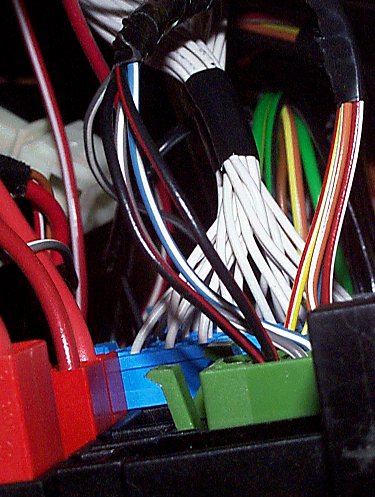 Go back under the dash and pull the 2 clips
upward that hold the fusepanel in place. These clips just pivot upward and don't actually
come off. The entire fusepanel will lift up slightly and then drop down. The panel has a
spool on each end that fits into a "J" shaped slot. Maneuver the fusepanel so
that you can see the right rear area of it as well as possible. Refer to the picture and
the diagram of the side/rear of the FP. Locate the 3 green connectors that are on the
right (passenger) side near the upper middle of the FP. A small mirror will help you to
see them.
Go back under the dash and pull the 2 clips
upward that hold the fusepanel in place. These clips just pivot upward and don't actually
come off. The entire fusepanel will lift up slightly and then drop down. The panel has a
spool on each end that fits into a "J" shaped slot. Maneuver the fusepanel so
that you can see the right rear area of it as well as possible. Refer to the picture and
the diagram of the side/rear of the FP. Locate the 3 green connectors that are on the
right (passenger) side near the upper middle of the FP. A small mirror will help you to
see them.